
Building a candy dispenser with AI, Raspberry Pi and Lego bricks
My son often asks me what is my job. It is not so easy for him (although it is not easier for my parents neither) to understand that I build softwares, even more with “AI” inside.
So I got this idea: why not building something that will give him a better and more concrete understanding? Okay, that’s great…but…what?
My previous work about Batman detection (see “Building a powerful Batman detector”) gave him more intuition but it still remained something like…magic!
Then I remembered that a few years ago one of my teammates made a candy dispenser connected to Twitter in order to release candies when there was a tweet posted with a special hashtag. I have decided to recycle this idea and adapt it to a new use case.
1. The User Story
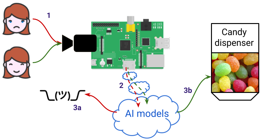
Let’s build Candybot, an automatic candy dispenser that will free candies if you are happy and smile at it. Very basic and simple yet enough challenging and interesting because:
- There is Computer Vision to be able to detect faces and then perform what is called Face Emotion Recognition (FER)
- As an additional challenge, it should run on an embedded device such as Raspberry Pi (#IoT)
- We have to find a way to control the dispenser motor
1.1. The use case step by step
Let’s now detail this user story a little bit more:
- Candybot might continuously read frames from the camera but it must not perform detection for each frame (it is useless, most of the time nobody will be in front of the camera) so the user must be able to launch the detection phase by pushing a “start” button.
- As the user cannot see on a screen if Candybot is actually doing something we must provide a visual feedback with some LEDs. For example:
- Candybot is in “idle” state: running but waiting for a detection trigger event (i.e. waiting for someone to press the button): LED is purple
- Picture has been taken and Candybot is processing it: LED is blue
- Candybot took the picture but did not detect that user is happy: LED is red
- Candybot took the picture and detected that user is happy: LED is green
- If detection is positive Candybot must interact with the candy dispenser motor to free some candies
- Candybot goes back to its “idle” state
Below is a video of what it looks like in the end: I have tested it with a picture of one smiling person.
Want to know how I did that? That is what I am going to share with you in this post!
1.2. Split it into pieces
Here are the things we will have to build in order to fit this need:
- Software part: a Face Detection and Face Emotion Recognition app
- Software/Hardware with Raspberry Pi:
- Write code that reacts on push button input
- Write code that lights a RGB Led with different colors
- Write code that runs a motor
- Make or buy: build or connect a candy dispenser
PREREQUISITES:
Here is a list of some prerequisites that are out of the scope of this post and so will not be further detailed:- A Raspberry Pi 4 device with latest Raspbian installed and updated
- A PiCamera connected to the Raspberry Pi
- SSH enabled to this Raspberry Pi
- Python virtualenv tool installed with:
- Opencv (follow this great post from Adrian Rosebrock - pay attention to his advice regarding the version)
- Tensorflow (make sure to install the ARM version even if pip tool should handle this for you)
- Keras (with prior fortran compiler and scipy installations - warning: this takes a while so you can grab a coffee)
2. Software part: a Face Detection and Face Emotion Recognition app
2.1. Building a modular app
This is obviously the most important part as it is the “brain” that controls everything. As there are quite a lot of stuff to do, if we want to build something that will be easy to maintain, adapt and maybe
change over time, the rule is to follow the Separation of Concerns principle (SoC)1.
It means that we will, as much as possible, isolate pieces of code depending on their purpose. Thus, the whole app is modular and changes in one specific part has no or very low impact on the rest of the app.
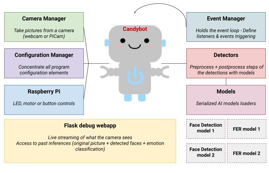
Here are the “modules” I have decided to build:
2.2. Good practice: externalize the configuration
An easy way to start with SoC principle is to externalize the configuration in an external file (JSON, YAML, INI, whatever) and delegates this to a “manager” that will handle the file loading and is responsible to
expose the values to the rest of the program.
In our case there are a lot of parameters that can be externalized: camera resolution, time between 2 tries, LED blinking time and so on.
But the most important thing is that this file is the single place where I declare all available models for Face Detection or Face Emotion Recognition.
And this makes the whole difference because it means that Candybot does not need to know which model is used: it relies on what is set in the configuration file.
In other words, AI models are interchangeable! It means that we can start with a model and if a new one is developed/found, it can be used with little-to-no change in the application code.
2.3. Candybot: the business logic
Candybot is the central piece of software, interacting with a lot of modules/components that does a single task:
- it retrieves configuration values from the Configuration Manager
- it interacts with the Camera Manager to take pictures
- it uses 2 Detectors (one for Face Detection, one for FER)
- it interacts with the Raspberry module if needed
Candybot is launched by the candybot_launcher script at startup and is given a mode argument to define whether it is running on a Raspberry Pi or not.
Yes: Candybot can run on a computer and use the webcam!
Debugging is then easier: feedback loop is much more faster than deploying the code on the Pi device and run it again and again.
Candybot knows this information only for one purpose: do not try to light up a LED or run a motor if the code is currently executed on a computer.
Starting Candybot is pretty straightforward:
python3 candybot_launcher.py --config-file ./config/config.json --log-file ./config/logging-console.json --mode pi
Then, in this candybot_launcher.py script the singleton2 is instanciated and the camera starts capturing frames:
# Start the candybot which is a Singleton
candybot = Candybot(mode)
candybot.start_camera()
Candybot’s methods:
# Starts a thread to continuously read frames from camera and store them in a
# thread-safe way so that they are accessible through a webapp for debugging purpose
def start_camera(self)

def stop_camera(self)
def set_status_ready(self)
def take_picture_from_camera(self) # The working logic for the candybot
def light_up_leds(self, color)
def start_motor(self)
At this time, Candybot is ready to be triggered for detections.
2.4. OK but how do we trigger the camera?
And here is where the Event Manager plays its role. We have here an infinite event loop (a “while True” loop if you prefer) with a listener that reacts on specific event. I said that Candybot can run on a computer so actually we have 2 types of listeners:
- KeyboardListener: used when running on a computer, reacts when a specific key is pressed. The pyinput package is perfect for that
- RaspButtonListener: used when running on the Pi device, uses GPIO pins and the GPIO.add_event_detect function to react when the physical button is pressed (more details in the Raspberry section later)
At startup, depending on the mode, one of this listener is started and the program is then waiting for user interaction:
# Start an event loop to react and interact with candybot
listener = KeyboardListener() if mode == cst.MODE_COMPUTER else RaspButtonListener()
listener.start()
Both listeners inherits from the EventLoop class and the common part is what happens next when there is event triggering:
class EventLoop(object):
  def __init__(self, name, mode, listener):
	self._bot = Candybot(mode)
	self._listener = listener

  def on_react_event(self):
	self._bot.take_picture_from_camera()

# Example with KeyboardListener
class KeyboardListener(EventLoop):
  def __init__(self):
	listener = keyboard.Listener(on_press=self._on_press, on_release=self._on_release)
	super().__init__("Keyboard_Listener", mode=cst.MODE_COMPUTER, listener=listener)

  def _on_press(self, key):
	try:
	  if key.char == 't':
	    self.on_react_event()
	except AttributeError:
	  ...
The EventLoop keeps a reference on Candybot (which is a Singleton2). It is the one that “asks” to Candybot to do something because user asked for it.
And here it is.
Here is a big picture of how those 2 key elements work together:
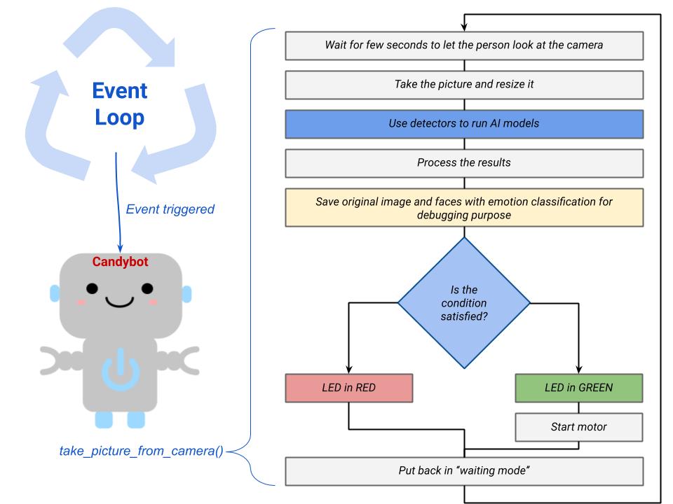
Here we can see the power of the SoC principle: “is_condition_satisfied” can be whatever you want. If, so far, it consists only in checking that the person is smiling on the picture it is easy
to change that and replace with, for example, a specific gesture recognition (eg. give candies only if the person has both hands up in the air).
We could also easily enrich with additional checks such as “did this person already take candies today?” with a face recognition step (to avoid feeding the kids with candies the whole day long ;-) ).
This would not break the whole code to do that. And this is cool. Really.
2.5. And what about AI models?
Train or use pre-trained models?
I have already tried some Computer Vision experiments but in this project my objective was more to combine different elements already available than building the most accurate models.
That is why I did not invest time in reinventing the wheel but instead used pre-trained models, at least for the V0 of the program.
With the software architecture in place, it will not be such a big deal to replace one model with another one if needed (remember the externalized configuration). There is still the option, as a further enhancement, to build and train AI models by myself.
Models usage
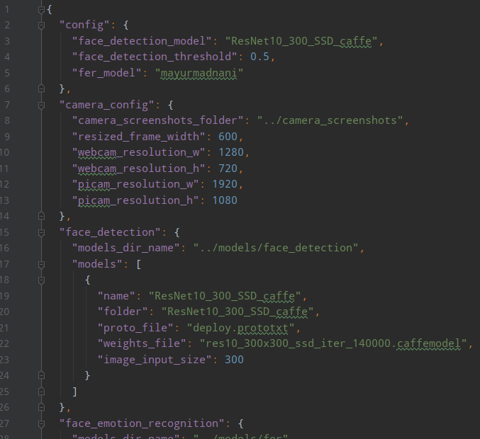
As explained earlier, everything is declared in config.jsonfile:
- what are the models to load at runtime to perform Face Detection or Face Emotion Recognition
- what are all models available for those tasks, paths to downloaded/serialized models and weights
Depending on the type of model it can be loaded through OpenCV with cv2.dnn.readNetFromTensorflow() or directly with model_from_json() from Keras package.
Those models are actually loaded by the detectors classes FaceDetector and FERDetector, using values returned by the program Configuration Manager:
# In Candybot constructor:
Candybot.__instance._face_detector = FaceDetector()
Candybot.__instance._fer_detector = FERDetector()

# FaceDetector constructor:
cfg = ProgramConfiguration()
self._model = cfg.get_face_detection_model()
self._threshold_confidence = cfg.get_face_detection_threshold()
Face Detection
This pyimagesearch blog post is a very good reading to start with: face detection with opencv. As explained by Adrian Rosebrock, we can use a pretrained model and load it through the OpenCV library, “all we have to do” is to wrap this call in our app and implement our business rules and logic.
Download section
Here are the links to use the Resnet-10 Single Shot Detector (SSD) caffe model that is used in pyimagesearch blog post:- caffe model
- deploy.prototxt file that describes the model in protobuf protocol
Face Emotion Recognition
Even though I were not always satisfied with the classification, I went with this model because the most important was to build a first version of the product. Moreover the author claims that it is small yet performant even on small device. Perfect for my use case!
Download section
The author gently provides the model on his github repository, weights have been saved in .h5 and model's architecture in JSON format so it is easy to load with the model_from_json function from Keras.3. Software/Hardware with Raspberry Pi
To interact with electronic components, we will massively use the GPIO Pins of the Raspberry Pi and control them with Python scripts throught the RPI.GPIO package3.
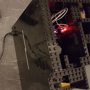
3.1. Visual feedback through RGB Led
RGB LEDs “have three tiny LEDs of 3 primary colors (red, green and blue) where a terminal is common for all. Some have common positive terminal (anode) and some have common negative terminal (cathode). When different voltage is applied to different LEDs, they make a mixture and produce several thousands of colors.” (Source).
What is great is that we use only one single component to output different colors. As we plan to have only 4 colors, we can use a all-or-nothing system.
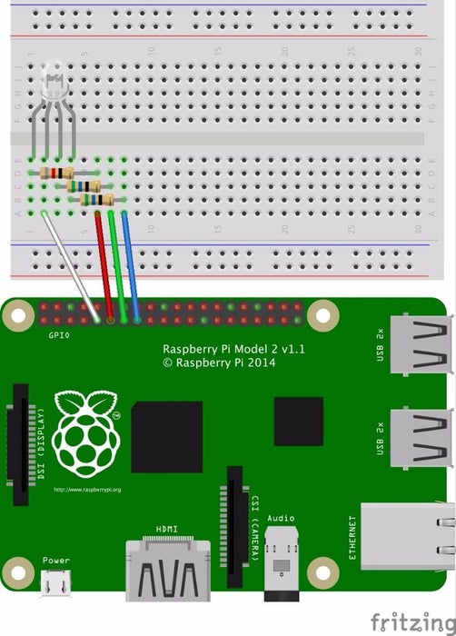
In my case I have common cathode (meaning that the LED has a shared ground) so circuit diagram is like the one on the right picture.
Ground on PIN9, Red on PIN 15 (GPIO22), Green on PIN 13 (GPIO 27), Blue on PIN 11( GPIO17), each of them with 330 ohms resistors in series, it works fine.
This guide4 to read resistor colors may be useful, as a gentle reminder ;-).
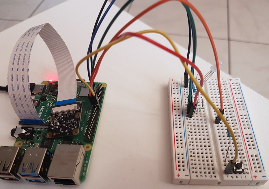
3.2. React on button pressed
Follow those instructions, it is very easy to put in place: one button, one resistor and here you are.
The button is connected to one PIN set as an input one and configured to detect edges (an edge is the transition from HIGH to LOW -falling edge- or LOW to HIGH -rising edge-). That’s all folks!
In terms of code, we use the GPIO.add_event_detect function to specify the callback function to call when there is a change in a state on this input PIN. This runs within an infinite loop:
# Add rising edge detection on a channel, ignoring further edges for 1s for switch bounce handling
GPIO.add_event_detect(pin.BTN_INPUT, GPIO.RISING, callback=self._callback, bouncetime=1000)
Pay attention to the bouncetime parameter which is used to control what is called ‘switch bounce’: without that, callbacks are called more than once for each button press5. Note that we could also handle that by adding a small capacitor in the circuit but the RPI.GPIO library offers this easier alternative with this parameter (time must be given in milliseconds).
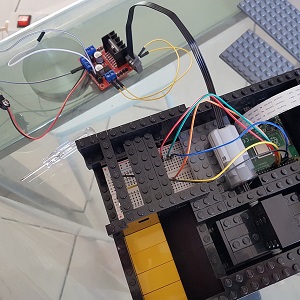
3.3. Controlling a motor
The first question is: what kind of motor? DC motor, stepper motor, servo motor?6
For this use case, I do not need precision so DC motor that rotates continuously is enough. There are a lot of resources78 to explain how to control direction or speed of a DC motor
but it is with this wonderful blog post of a dad that built a Raspberry Pi powered LEGO car that I have been able to
put everything in place.
“So in researching motor control, the general advice was that motors require too much voltage and current to be driven directly from the Raspberry Pi. The most common advice was to use a motor controller chip”.
As advised by the author I bought this cheap L298N H-Bridge module, a simple way to achieve that. Coupling the L298N H-Bridge9 to the Pi device give us the ability to control both the speed
and rotation direction of two DC motors.
Usage is pretty straightforward: when input 1 is high and input 2 is low, the motor turns in one direction. When input 1 low and input 2 high turns the motor in the other direction10.
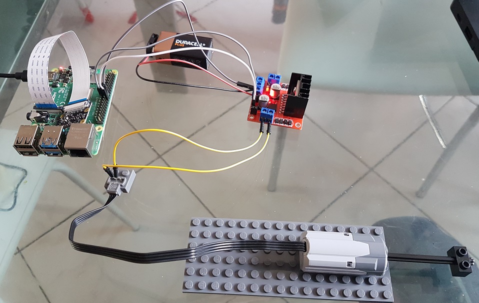
WARNING
In order to protect the Pi, it is highly advised to use another power source (such as a battery) for the motor and to put the battery and Pi ground in common instead of relying on +5v output. That is what I did.
3.4. Connected pins
Connections for this use case are not so complicated but we need such a picture to do the mapping between PIN numbers and GPIO numbering because they are different (thank you insane people that had this great idea that is driving us litterally crazy).
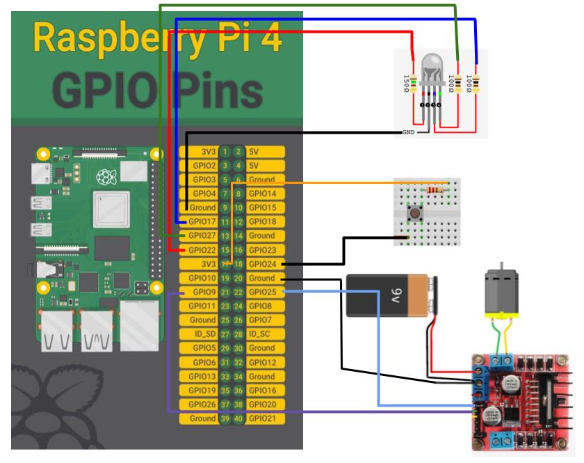
RGB LED
- PIN9 (Gnd) to common cathode RGB Led
- PIN11 (GPIO17) to B of RGB Led
- PIN13 (GPIO27) to G of RGB Led
- PIN15 (GPIO22) to R of RGB Led
Button
- PIN17 (+3.3V) to resistor
- PIN18 (GPIO24) to input button
Motor control
- PIN20 (Gnd) to common ground of L298N
- PIN21 (GPIO9) to IN3 of L298N
- PIN22 (GPIO25) to IN4 of L298N
Run at boot
The Pi device may not be running 100% of the time but it will not be user-friendly to connect through SSH each time the Raspberry Pi boots in order to launch the program. Just write down a init.d shell script that will be
executed at startup11.
4. Make or buy: build or connect a candy dispenser?
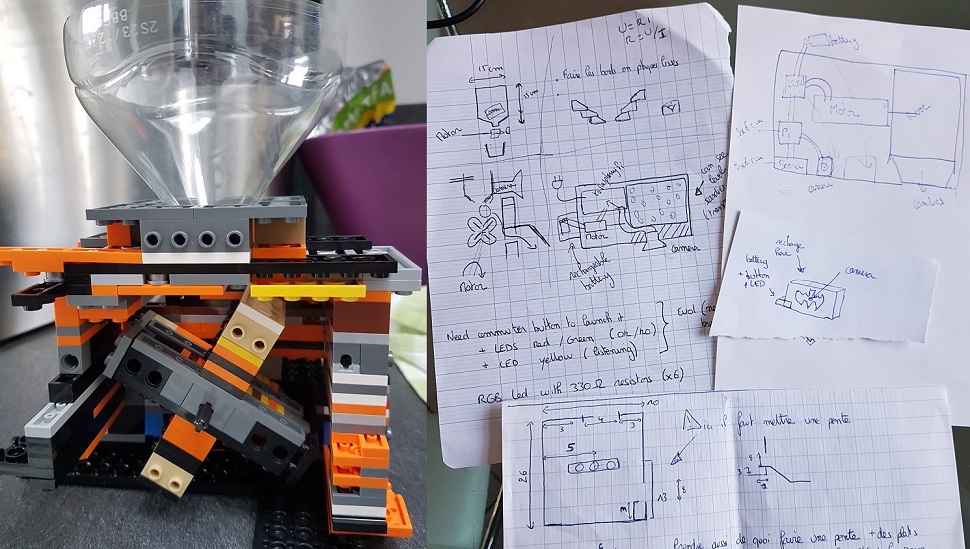
I first wanted to buy a candy dispenser and control its motor (or its opening mechanism) with a servo motor. I have not found something I liked so I decided to build my own candy dispenser with….Lego bricks! And so, why not, being in the end able to build a Batman Candy dispenser (life achievement ;-)).
There are different possibilities for the delivery mechanism:
- a hatch that opens but main issue is that it will let everything out
- a kind of propeller which turns and lets pass candies little by little. Here the main problem is that it is necessary to calculate the distances not to crush candies while being certain to let only few pass. This prevents having candies of different sizes and that could also be an issue
- a mechanism that can be found on many videos with a hole and a spring
4.1. Prototyping
Here are some video examples for 2nd and 3rd options.
I have decided to give a try to the 2nd option, so I borrowed my son’s X-Wing Lego bricks to build my first prototype:
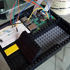
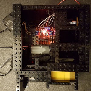
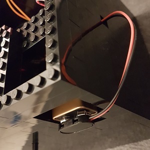
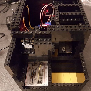
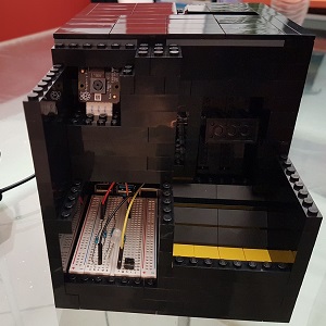
4.2. A candy dispenser under construction!
Below is a gallery of pictures I took during the construction:
5. Bonus track: the debug app!
As there is no screen, it is not easy to understand why Candybot decided to free (or not) the candies so I built an embedded webapp with 2 features:
- a live streaming feed in order to see in real time what the PiCamera sees
- a page to list all inferences (predictions) made and the possibility to see all pictures for one specific inference.
This webapp is made with Flask and, yet basic, is very helpful in order to debug the program. You will see this app in action in videos below.
When Candybot starts, the web server is also starting and available at <ip.address>:3001.
6. Time to test it!
In this section you will find videos of different tests and associated logs. In the end, a last video is exploring inference results with the debug app.
For those tests, I took pictures from fashion magazines or flyers.
6.1. No smile = no candies!
Associated logs for this try:
11:56:28,419 - Candybot - INFO - Taking picture with the camera
11:56:28,419 - Candybot - INFO - Blinking RGB LED for 2 seconds
11:56:30,687 - Candybot - INFO - Frame acquired, start processing it
11:56:30,687 - Candybot - INFO - Performing face detection with model 'ResNet10_300_SSD_caffe'
11:56:31,257 - Face_Detector - INFO - Forward pass took 0.53619 seconds
11:56:31,257 - Face_Detector - INFO - Found 109 predictions
11:56:31,262 - Candybot - INFO - Performing face emotion recognition with model 'mayurmadnani'
11:56:32,050 - FER_Detector - INFO - Face 0/1 - FER step took 0.7866 seconds
11:56:32,068 - Candybot - INFO - Analyzing all detected faces and emotions. Found 1 faces to analyze
11:56:32,069 - Candybot - INFO - Detected emotion for people 1 is 'Sad'
11:56:32,189 - Candybot - INFO - For this picture, all detected faces are happy? --> False
11:56:32,189 - Candybot - INFO - Lighting RGB LED with color for status 'KO'
11:56:33,190 - Candybot - INFO - Lighting RGB LED with color for status 'READY'
The whole process takes around 5 seconds with 2s of waiting time. For both models, inference is made in less than 1 second for each, this is very good!
6.2. One smiling person
Associated logs for this try:
...
12:07:08,297 - Candybot - INFO - Performing face detection with model 'ResNet10_300_SSD_caffe'
12:07:08,372 - Face_Detector - INFO - Model ResNet10_300_SSD_caffe - Computing detections...
12:07:08,954 - Face_Detector - INFO - Forward pass took 0.57987 seconds
12:07:08,954 - Face_Detector - INFO - Found 146 predictions
12:07:08,958 - Candybot - INFO - Performing face emotion recognition with model 'mayurmadnani'
12:07:09,091 - FER_Detector - INFO - Face 0/1 - FER step took 0.13283 seconds
12:07:09,092 - Candybot - INFO - Analyzing all detected faces and emotions. Found 1 faces to analyze
12:07:09,092 - Candybot - INFO - Detected emotion for people 1 is 'Happy'
12:07:09,221 - Candybot - INFO - For this picture, all detected faces are happy? --> True
12:07:09,222 - Candybot - INFO - Lighting RGB LED with color for status 'OK'
12:07:09,222 - Candybot - INFO - Starting the motor for 0.5 seconds
12:07:10,730 - Candybot - INFO - Lighting RGB LED with color for status 'READY'
6.3. More than one person
If Candybot detects more than one person, then all have to smile/be detected as Happy in order to free candies.
Associated logs for this try:
...
12:09:39,680 - Candybot - INFO - Performing face emotion recognition with model 'mayurmadnani'
12:09:39,796 - FER_Detector - INFO - Face 0/2 - FER step took 0.11461 seconds
12:09:39,906 - FER_Detector - INFO - Face 1/2 - FER step took 0.10939 seconds
12:09:39,907 - Candybot - INFO - Analyzing all detected faces and emotions. Found 2 faces to analyze
12:09:39,907 - Candybot - INFO - Detected emotion for people 1 is 'Happy'
12:09:39,907 - Candybot - INFO - Detected emotion for people 2 is 'Happy'
12:09:40,004 - Candybot - INFO - For this picture, all detected faces are happy? --> True
12:09:40,005 - Candybot - INFO - Lighting RGB LED with color for status 'OK'
12:09:40,005 - Candybot - INFO - Starting the motor for 0.5 seconds
12:09:41,507 - Candybot - INFO - Lighting RGB LED with color for status 'READY'
6.4. Access to inference results
WRAP-UP
Building Candybot is a personal initiative that took several weeks of my free time and made me really nervous sometimes (I stopped counting how many times I had to change the Lego structure for example…) but I am happy and proud of the achievement. More than that, I have been able to explain (roughly) to my son each step and I hope he has now a better understanding of what “building softwares” means. It was also the possibility for me to teach him that we do not always have to buy stuff, we can try to understand how things work and have fun building them by ourselves.
This project was also a good experience about embedded AI (on-device inference): constraints about limited resources and computation power is an additional step we have to take into account and it is more than ever a trade-off between accuracy and inference time when choosing models, their language and their size.
As usual, here are some possible further improvements:
- change AI FER model or train my own one with available public datasets
- train a model to recognize my kids and add a check to avoid giving too much candies to the same kid within the same day
- Candybot could act as home watcher also and track movements in the room while I am away from home
Thanks for reading. If you enjoyed it, feel free to leave a comment below.
Author: nidragedd
Feel free to leave a (nice) comment if you want
Required fields are marked *